A month or so back I attended Hack In The Box 2013 in Amsterdam. I do a fair bit of work with mobile and have done my share of 'BYOD', 'MDM' and 'MAM' (and probably any other MxM that comes along). I decided if I was gonna take the time to attend the con it would be worth signing up for some of the training too. The obvious choice for me was Mobile Hacking II which was being run by Blake Turrentine from Hotwan. He had enlisted the help of two great iOS hackers, @pod2g and @p0sixninja. Both have made regular contributions to iOS jailbreaking and know a lot about iOS.
One of the topics @p0sixninja covered was finding bugs in iBoot. To do this you need a special USB to serial 30 pin connector. This isn't new, it's an area @i0n1c did a lot of the initial research on back in 2011. He also presented his findings at Blackhat (http://media.blackhat.com/bh-us-11/Esser/BH_US_11_Esser_Exploiting_The_iOS_Kernel_Slides.pdf). He discovered that you could create a USB serial cable that would allow you to connect to the iOS kernel via KDB and debug what was going on. In order to do this you obviously need to create the USB cable, I don't have one so decided to order the parts and try to knock one up. @HackerFantastic has a good write up over on instructables (http://www.instructables.com/id/Apple-iOS-SerialUSB-Cable-for-Kernel-Debugging/?ALLSTEPS) that is also well worth a look.
Here are my instructions and what I did….
Ingredients:
You will need the following components in order to create the USB serial debugging cable.
1 x PodGizmo (30pin) (http://proto-pic.co.uk/podbreakout/)

1 x FT232RL USB to Serial Breakout Board (http://proto-pic.co.uk/breakout-board-for-ft232rl-usb-to-serial/)

1 x 470KΩ resistor (http://proto-pic.co.uk/470-ohm-1-4-watt-pth/)

2 x USB Cables (A to mini B) (http://proto-pic.co.uk/sparkfun-usb-mini-b-cable-6-foot/)

Single Core Hook up Wire / Bell Wire (http://proto-pic.co.uk/hook-up-wire-assortment-solid-core/)

Utensils:
Wire Cutters
Soldering Iron
Solder
3 x pairs of hands and patience (if you haven't soldered before).
I cocked up and didn't get the 'Single core Bell / Hook up wire'. Being a bit impatient and waiting to give this a go asap I decided to try using some dodgy old flex from a 240v lamp (see picture), my soldering skills aren't great but trying to do it this way was a nightmare.

My first tip would be buy your self some hook up wire or single core bell wire. I ended up running to Maplin the next day to get some as it was turning into a train smash. This is what I purchased http://www.maplin.co.uk/solid-core-wire-1-0.6-6187.
Following the steps below you should be able to create a cable similar to the one I have:
Step 1 - Cut 4 pieces of bell wire about 3 cm's in length and strip back a small amount on each end.
Step 2 - Tin each end of the bell wire using the soldering iron (if you haven't soldered before this might help http://www.instructables.com/id/Strip-and-Tin-Wires-Like-a-Pro/)
Step 3 - Solder a piece of the bell wire to each of the GND / RX / TX / 3.3v pins on the USB to serial break out board.

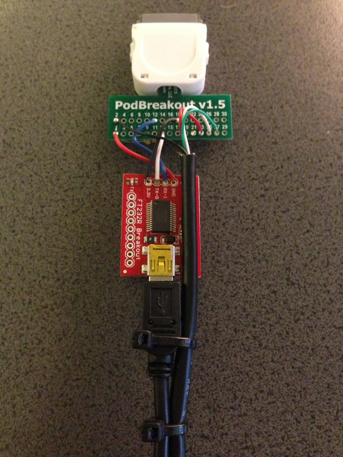
Step 4 - Solder one end of the resister and the wire connected to the GND pin on the serial break out board to pin 1 on the pod break out board (In the picture below Red Cable to pin 1). This bit is a real PITA as you have to manage both the resistor and the wire whilst trying to solder.
Step 5 - Solder the wire in RX pin on the USB to serial break out board to pin 12 on the pod breakout board (In the picture below Blue cable to pin 12).
Step 6 - Solder the wire in TX pin on the USB to serial break out board to pin 13 on the pod breakout board (in the picture below White cable to pin 13).
Step 7 - Solder the wire in 3.3v pin on the USB to serial break out board to pin18 on the pod breakout board (in the picture below Black cable to pin 18).

Step 8 - Solder the loose end of the resistor to pin 21 on the pod break out board.
Step 9 - Cut the end of a usb cable and strip back the shielding cable to show the 4 wires of the USB cable, these will likely be black, red, white and green.
Step 10 - Tin the ends of each of the black, red, white and green USB wires.
Step 11 - Solder the black USB cable to pin 2 on the pod break out board.
Step 12 - Solder the red USB cable to pin 23 on the pod break out board.
Step 13 - Solder the white USB cable to pin 25 on the pod break out board.
Step 14 - Solder the green USB cable to pin 27 on the pod break out board.
The finished iOS Kernel debugging cable should look like this (I added some cable ties to hold it together a bit).

If you connect an iPhone or iPad (30pin connector not 5 or Mini) to the pod break out and then plug the usb cables into your mac you should see the devices under USB as below:

I have also tried to create a video of the first 2/3 of the process as I ran out of memory on the iPad I was recording on, and my "ginga" barnet gets in the way a lot... It doesn't include the soldering of the USB cable wires to the pod breakout board but part of the process is there. Unfortunately it's not great, my soldering skills are now marginally better than the camera skills ;-)
Hopefully I'll get some time to play with iBoot and write a fuzzer for the kernel...
Good idea, i will wait this way
ReplyDelete